Circuits
Create adds several components that can be used in redstone circuits. These include the Redstone Contact, Redstone Link, Link Controller, Pulse Repeater, Pulse Extender, Powered Latch, and Powered Toggle Latch. These components can make redstone circuits simpler and smaller as well as giving finer control over timing.
Logic Gates
Logic gates are circuits that provide a digital output signal based on the conditions of one or more input signals. Digital signals are either on or off (powered or unpowered redstone) and usually represented as a 1 or 0 respectively.
NOT GATE
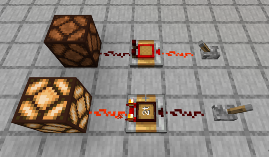
The ability to place the Pulse Extender in an inverse output mode allows it to be used as a NOT gate. Simply set the pulse length to 2 ticks (or as needed for your particular circuit) and right click the Pulse Extender to toggle to inverse mode.

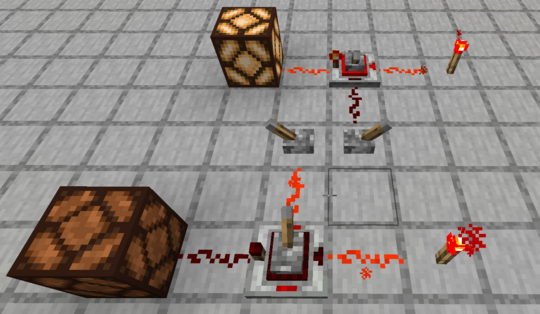
A Powered Latch can also be used for a NOT gate. A continuously powered signal is sent to the set input and the control signal is sent to the reset input.

AND, OR, NAND, and NOR Gates

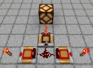
A simple pattern of three Pulse Extenders can act as an AND, OR, NAND, or NOR gate depending only on the selection of inverse settings among the Pulse Extenders. If we label the two input Pulse Extenders A and B, and the output O, then the following table shows the Normal (N) versus Inverse (I) setting of each Pulse Extender to achieve the indicated gate.
| GATE | A | B | O |
|---|---|---|---|
| AND | I | I | I |
| NAND | I | I | N |
| OR | N | N | N |
| NOR | N | N | I |