Circuits
Create adds several components that can be used in redstone circuits. These include the Redstone Contact, Redstone Link, Linked Controller, Pulse Repeater, Pulse Extender, Powered Latch, and Powered Toggle Latch. These components can make redstone circuits simpler and smaller as well as giving finer control over timing.
Logic Gates[edit | edit source]
Logic gates are circuits that provide a digital output signal based on the conditions of one or more input signals. Digital signals are either on or off (powered or unpowered redstone) and usually represented as a 1 or 0 respectively.
NOT GATE[edit | edit source]
The ability to place the Pulse Extender in an inverse output mode allows it to be used as a NOT gate. Simply set the pulse length to 2 ticks (or as needed for your particular circuit) and right click the Pulse Extender to toggle to inverse mode.
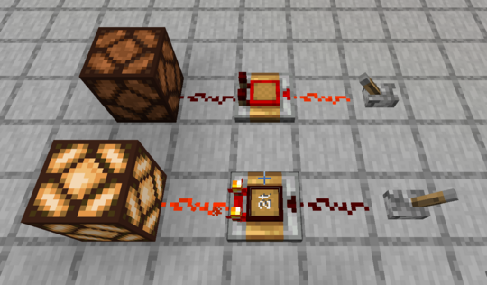
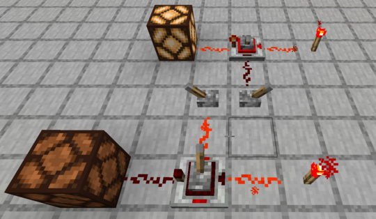
A Powered Latch can also be used for a NOT gate. A continuously powered signal is sent to the set input and the control signal is sent to the reset input.
AND, OR, NAND, and NOR Gates[edit | edit source]
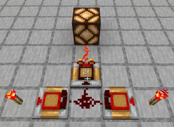
A simple pattern of three Pulse Extenders can act as an AND, OR, NAND, or NOR gate depending only on the selection of inverse settings among the Pulse Extenders. If we label the two input Pulse Extenders A and B, and the output O, then the following table shows the Normal (N) versus Inverse (I) setting of each Pulse Extender to achieve the indicated gate. (Note that there are smaller circuit options for some of the gates.)
|
 |
XOR Gate[edit | edit source]
Pulse Extenders can be used to create a single layer XOR Gate. The design shown below uses repeaters to push charges into opaque blocks which act as diodes providing isolated signals to both the redstone dust continuing to the right and the redstone dust between the two blocks. The center Pulse Extender injects a signal into another block which also acts as an isolating diode forming independent OR Gates with the redstone dust on the far side and near side of the block. All three of the Pulse Extenders are in the inverted mode.

Clocks[edit | edit source]
Pulse Clock[edit | edit source]
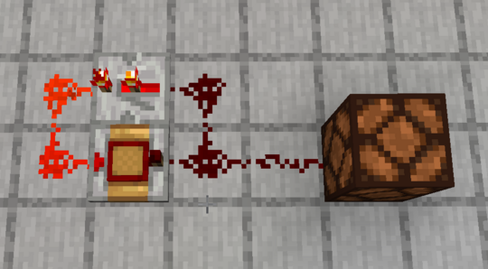
A Pulse Repeater along with a Redstone Repeater can make a pulse clock where a short pulse is repeatedly sent out with a selectable delay between pulses. In the clock shown below, the Redstone Repeater must have at least 1 tick delay. A pulse input on any of the redstone lines will start the clock. Note that the pulse from a button is too long and will interfere with the feedback signal from the repeater. To start the clock, you can quickly switch a lever on and off or you can feed a button output through another Pulse Repeater set to 2 ticks. The delay between pulses is controlled by the delay setting on the Pulse Repeater.
Variable Cycle Clock[edit | edit source]
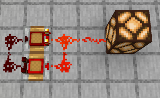
Two pulse extenders, one in inverse mode, can make a clock with independently settable on and off durations. The clock will start itself when one of the two pulse extenders is set to inverse mode.
Signal Comparators[edit | edit source]
Signal comparators compare the strength of two input signals from which they output a signal based on the similarity or difference in the two input signals.
Matching Signal-Strength Detector[edit | edit source]
A matching signal-strength detector emits a signal when the strengths of two input signals are equal. When the input signals are unequal, the detector output is off.
The circuit shown below will detect matching signal strengths between 1 and 15. In this circuit, the comparator on the right is in subtraction mode, causing it to subtract the strength of the signal entering the side from the strength of the signal entering the base. The circuit will trigger an output signal when the output of the comparator on the right is of strength one. This means the left side signal must be reduced by one, which is done here by the string of two redstone dust.
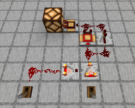
The output of the subtraction comparator is fed to a pulse extender acting as an inverter and a repeater acting as a one-way diode. The output of these two devices is ORed then input to another pulse extender acting as an inverter. The circuit output will be ON only when the outputs of both the pulse extender and the repeater are off. This condition will occur only when the output power of the subtraction comparator is exactly one, powering the pulse extender inverter but not the repeater.
If the strength of the side signal is greater than the base signal, the subtraction will be negative. The comparator will put out no signal. The pulse extender inverter will therefore output a signal which then turns off the circuit's final output. If the strength of the side signal is less than the base signal, then the subtraction comparator will put out a signal strength of at least two, thus ensuring that both the pulse extender inverter and the repeater are powered. In this case, the signal from the repeater turns off the circuit's final output.
This simple circuit will not detect matching strengths of zero. Also, if the left signal is zero and the right signal is one, the circuit will give a false positive result. Care must be taken that the left side signal never be less than one.
One use for a matching strength detector is to create a combination lock. Only when a player sets the proper signal strength will a desired action occur. Multiple circuits can be ORed together prior to the final inverter to create a multi-digit combination lock.